ASME B31.8 Gas Pipeline Wall Thickness & Span Calculator (Excel Dashboard)
Originally published: 31/08/2026 11:12
Last version published: 12/10/2026 12:37
Publication number: ELQ-54561-2
View all versions & Certificate
certified

ASME B31.8 Gas Pipeline Wall Thickness & Span Calculator (Excel Dashboard)

Check gas pipeline wall thickness per ASME B31.8 with location-class design factors: instant PASS/FAIL, max support span, collapse pressure.

Description
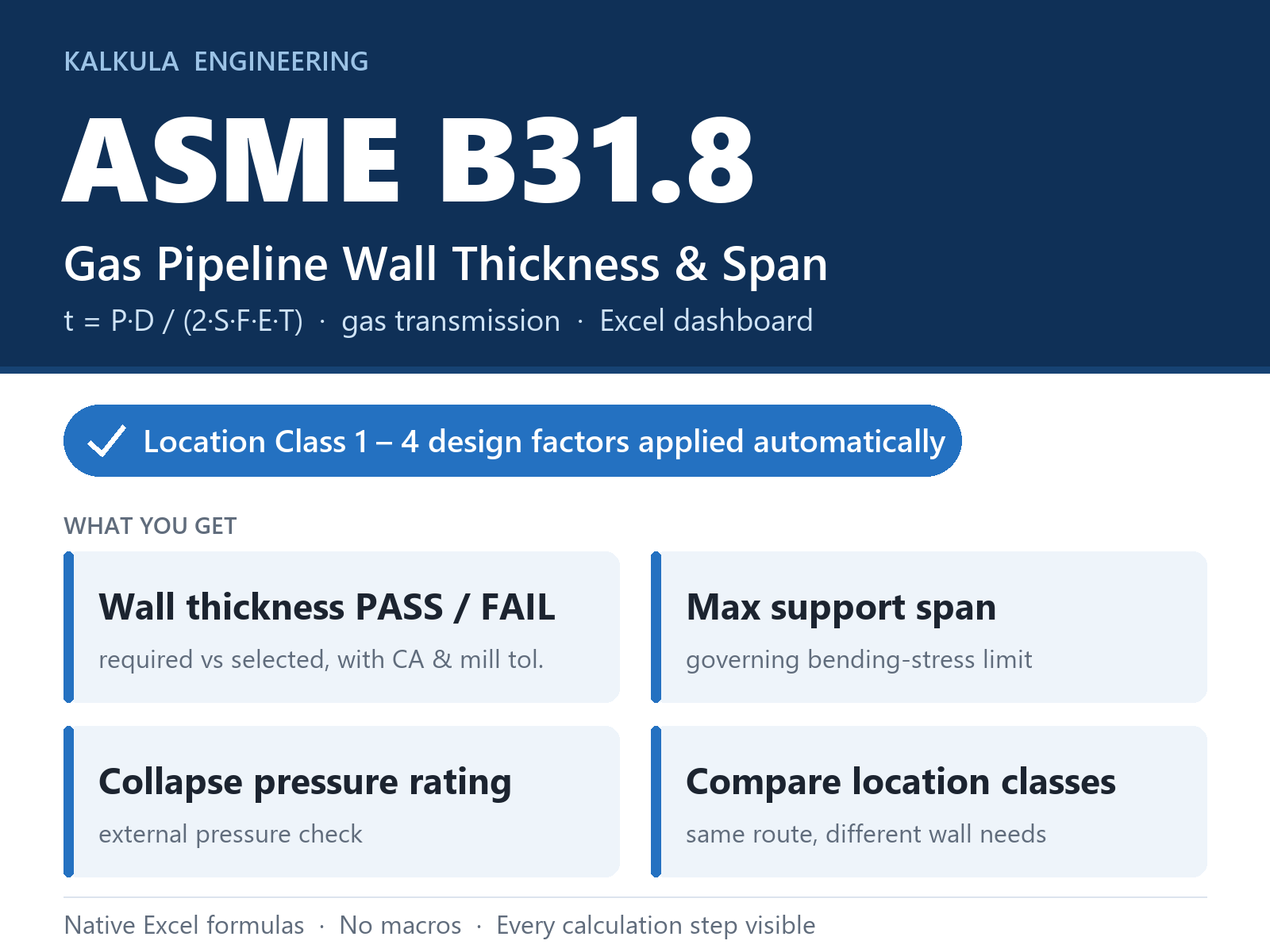
Built on ASME B31.8's pressure-design equation for gas transmission pipelines: t = P·Do / (2·S·F·E·T), per para 841.1. Unlike B31.4's fixed design factor, B31.8 scales allowable stress by location class — the same pipe can need a different wall thickness depending on where it runs.
Enter design pressure, pipe inside diameter, trial wall thickness, corrosion allowance and mill tolerance, then select a pipe grade (12 built in, or custom SMYS/UTS), weld joint type and location class (Class 1 Div 1/2 through Class 4). Strength, joint factor and design factor F resolve automatically.
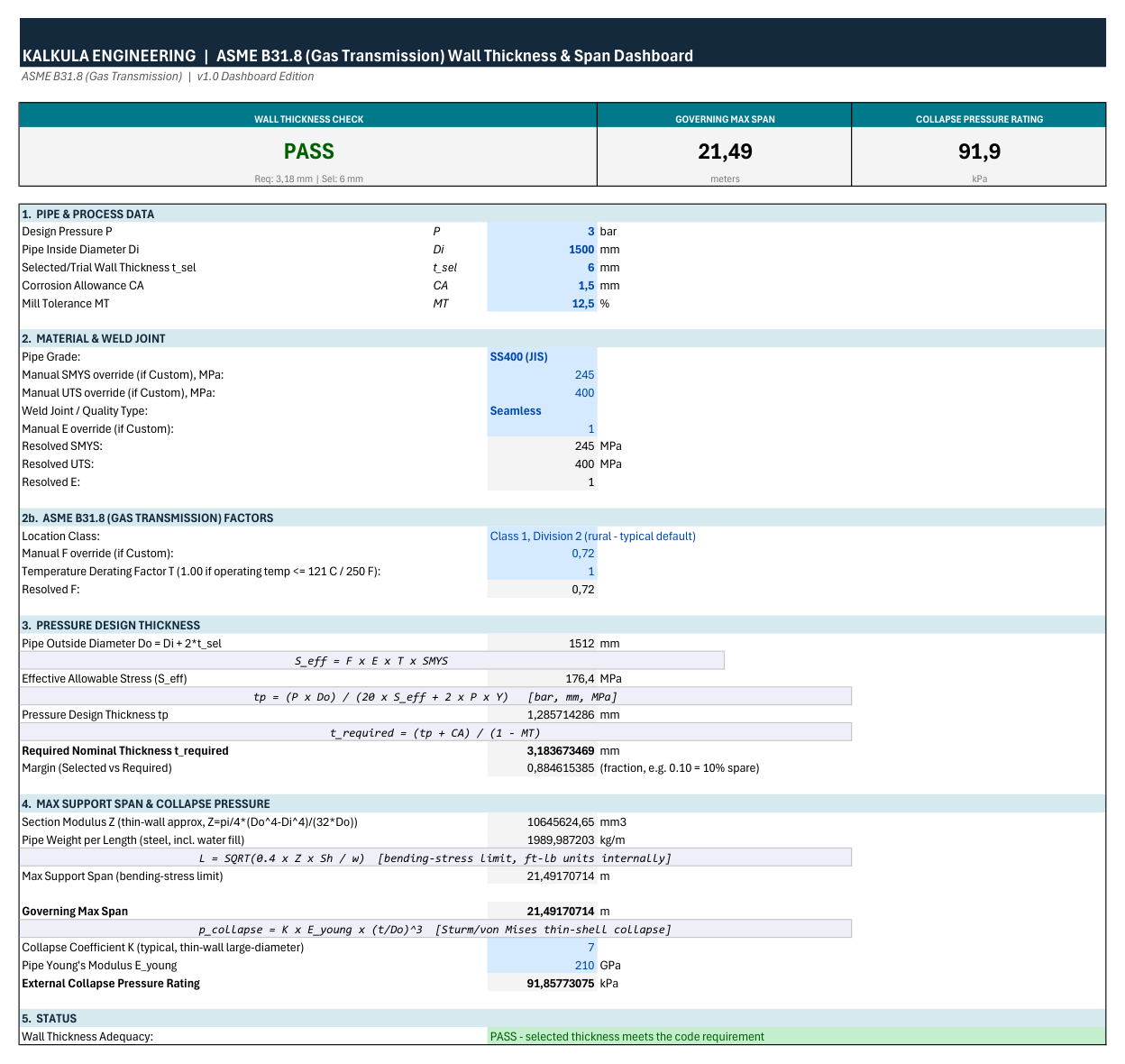
Three KPI cards give the verdict at a glance:
• Wall thickness check — PASS/FAIL against required nominal thickness
• Governing max span — bending-stress support span limit
• Collapse pressure rating — external collapse pressure (thin-shell)
How to use:
1. Enter pressure and pipe geometry in the blue input cells (bar, mm, %).
2. Pick pipe grade, weld joint type and location class; override F or T manually if your case needs it.
3. Read the three KPI cards. The calculation trail underneath shows allowable stress, pressure design thickness, required nominal thickness and margin, so a checker can follow it line by line.
Useful for comparing wall thickness needs across location classes on the same route.
Limitations: temperature derating T = 1.00 is valid only up to 121°C / 250°F — the elevated-temperature T table is not included. The weld joint factor (E) uses common reference categories. Span and collapse checks are general engineering estimates. Not affiliated with or endorsed by ASME.

This Best Practice includes
1 Excel workbook (.xlsx, no macros): Dashboard, Lookup tables, Read Me. Editable formulas, 12 built-in pipe grades.

Acquire business license for $10.00

Add to cart

Add to bookmarks

Discuss

Further information

Quickly verify that a gas transmission pipeline's wall thickness meets ASME B31.8 pressure-design requirements — accounting for population-density location class — and check the governing max support span and external collapse pressure rating, with an instant PASS/FAIL verdict.

Preliminary wall thickness sizing or verification for gas transmission pipelines under ASME B31.8, across any location class (rural to urban). Works with common line pipe grades or custom SMYS/UTS input. Useful for quick sizing checks, design reviews, and comparing wall thickness needs across different location classes for the same pipeline route.

Not for liquid/slurry pipelines (ASME B31.4) or process/plant piping (ASME B31.3) — different design factors apply. Not valid as-is for elevated-temperature service above 121°C/250°F (needs the code's T-factor table, not included). Not a substitute for final stamped engineering design — results should be confirmed by a certified/PE engineer against the current ASME B31.8 edition.


0.0 / 5 (0 votes)

please wait...